3D / WEBGL · CONFIGURATOR · LIVE
CARPORT CONFIGURATOR
6,000 × 3,600 MM · 38 × 38 × 1.2 SQUARE TUBE · 13 + 9 STOCK BARS
A steel carport as a product page would need it: every tube is a part with a blank, a finished length, a stock bar and a start position. Rotate the frame, click a tube in the model or in the cut plan, switch the roof between shade net and sheet in three finishes, and put in your own price per bar. Bill of materials, cut plan, CSV exports and the 3D geometry all read one data source.
An example with one fixed size · what BOS builds to measure →
- Posts
- Rails
- Beams
- Ridge
- Braces
- Roof tubes
Geometric planning, not a structural proof. Collisions, end faces and cut sums are verified. Load-bearing, wind, anchoring and welds are not. 2,400 mm is the outer frame height, not the clearance: the beam underside sits at 2,362 mm and the braces narrow the top corners.
Cut plan · base frame
13 stock bars
Every row is one 6,000 mm bar. Coloured segments are blanks, the cyan marks are 3 mm cuts, the empty end is the remnant. Click a segment to select the part.
78,000 = 75,060 + 93 + 2,847 mm — blanks + 31 straight cuts + remnants. The mitred brace ends are worked inside the 600 mm blanks.
Bars 1–5 stay uncut: they need 6,000 mm of usable length and clean factory ends. If they have to be trimmed, the plan changes.
Alternative · sheet roof
+ 9 bars, 14 tubes
Eight sloped rafters from 1,820 mm blanks — finished 1,809.406 mm axial, both ends mitred 4.764° — and six purlins of 6,000 mm, uncut. Same 38 × 38 × 1.2 profile as the base frame, as a geometric approach.
Two roof fields of 6,200 × 1,906.586 mm on the slope, 23.642 m² together, 100 mm overhang all round. Not an order quantity: cover width, side lap and waste are missing.
54,000 = 50,560 + 24 + 3,416 mm. Bars 14–19 uncut; bars 20–21 carry 3 × 1,820 with 531 mm left; bar 22 carries 2 × 1,820 with 2,354 mm left.
Only 4.764° of pitch — check the minimum pitch of the chosen sheet system. The extra load and wind uplift are not sized; the tubes do not prove the frame adequate.
Bill of materials
Steel only
| Part | Qty | Blank each | Total |
|---|---|---|---|
| Upper side rail | 2 | 6,000 mm | 12,000 mm |
| Bottom side rail | 2 | 6,000 mm | 12,000 mm |
| Ridge rail | 1 | 6,000 mm | 6,000 mm |
| Side post | 8 | 2,324 mm | 18,592 mm |
| Top cross beam | 4 | 3,524 mm | 14,096 mm |
| Rear floor tie | 1 | 3,524 mm | 3,524 mm |
| Diagonal brace blanks | 14 | 600 mm | 8,400 mm |
| Short ridge post | 4 | 112 mm | 448 mm |
| Total | 36 | 75,060 mm |
- Base frame · 13 bars
- $520
- With one spare bar · 14
- $560
- Incl. sheet-roof tubes · 22 bars
- $880
13 bars is also the length floor: 75,060 / 6,000 = 12.51, rounded up. The verified plan reaches it.
Not priced
Shade net or sheet, fixings, anchors, wedges, welding consumables, cutting discs, corrosion protection and labour.
Ideal roof-net area over the top edges ≈ 21.676 m²; two closed gables to 2,400 mm together 17.280 m², two closed long sides together 28.800 m². Geometric areas — no hems, overlaps or waste.
45° braces
From blank to joint
All 14 braces share one end geometry: blank 600 mm, finished axial extent 588 mm, axis 550 mm between the connection faces. The mitres are opposite-handed, 45° each, no extra swivel.
38 mm of profile at 45° gives 38√2 = 53.740 mm of contact on each face. The axis meets the face 550 / √2 = 388.909 mm from the inner corner; the contact runs from 362.039 to 415.779 mm.
Outer edge 588 mm, inner edge 512 mm. 6 mm of blank remain in front of and behind the finished envelope — enough for a 3 mm kerf square to the 45° blade (3√2 = 4.243 mm axial).
Verified · open
What the model proves
Geometry and cutting
Every pair of steel parts was tested for volume overlap with a separating-axis test on its convex hull: none. All 62 end faces of the 31 cut parts land fully on a neighbouring tube face. Each of the 50 blanks is assigned to exactly one bar, and every bar closes including its kerfs. That is geometry — it says nothing about whether the structure stands.
Open by design
Stability, deflection, loads, weld execution, base plates and anchoring are open. The net is shade, not a watertight roof; the roll-up ends are a concept without a mechanism. The reference vehicle is a generic, unbranded, stylised 4×4 at 3,923 × 1,976 × 2,124 mm, freely scaled and for scale only — door clearance is unchecked.
An example · the real thing is built to measure
What a commission can include
This configurator shows one size, one material and one roof in two variants. It is an example of what BOS builds for manufacturers, dealers and workshops: one tool that derives model, cut plan, bill of materials and exports from a single data source. Nothing on the list below is part of this example. It describes what a commission can cover.
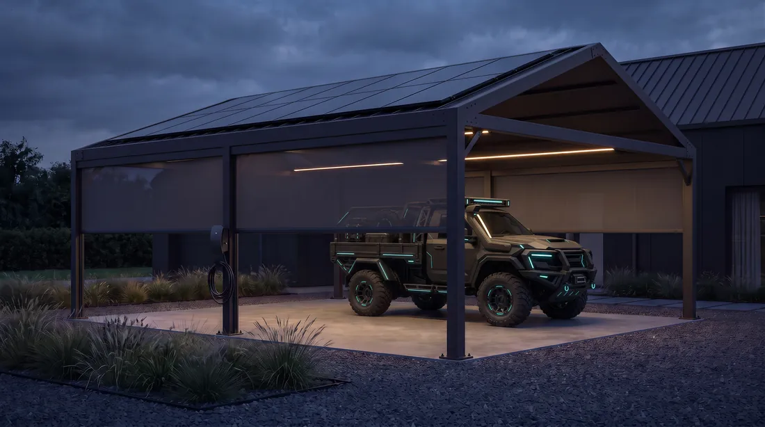
- Solar roof
- Side shade screens
- Light lines
- EV charger
- Rear screen
- Frame to measure
AI-generated This picture is a concept visual made with generative AI — no photograph of a real product, place or person.
Free dimensions
Length, width, height and stock length as inputs. Parts, cut plan, remnants and totals recalculate in the browser on every change.
Your product logic
Profiles, roof types, wall elements and accessories from your range, with the rules for what fits what.
Prices and enquiry
Your price list instead of an example figure, a quote as PDF, and an enquiry that carries the chosen configuration with it.
Sun position and shade
The shadow cast by date, time and latitude — for the net, the sheet and the lowered net ends.
Data for production
Bills of materials, cut plans and part labels as CSV and PDF, the model as a 3D file for CAD and visualisation.
A check on every change
Collisions, end faces and cut sums are verified by the tool itself. The structural proof comes from an engineer, not from software.
Scope, time and price are in the quote. On the rate card the way in is called Custom Engagement.
Request a configurator →All dimensions in mm. CSV files: UTF-8, comma-separated.